For residential and light commercial users, an electric utility company supplies single-phase or three-phase power to users at voltages from 115 volts to 460 volts. Voltage systems vary from one locality to another. If in doubt about the correct input voltage, contact the local utility company. Typical A C input voltage systems that will be encountered when servicing HVAC equipment include the following:
• 115 volt, single-phase
• 120/240 volt, single-phase, 60 Hz
• 208/230 volt, single-phase, 60 Hz
• 208/230 volt, three-phase, 60 Hz
• 460 volt, three-phase, 60 Hz
Input Voltage Measurements
Input voltage measurements are made to determine if the proper source voltage is being supplied to a unit in order for it to operate efficiently and economically. Input voltage checks are usually the first test made when troubleshooting electrical problems.
Effects of High and Low Input Voltage
Too high or too low an operating voltage can cause overheating and possible failure of a motor. Operating voltages applied to motors and other electrical components must be maintained within minimum-maximum limits from the voltage value given on the component’s nameplate. If the operating voltage falls outside these limits, the system should be turned off and the problem corrected before restarting the system. The problem may be with the building distribution system or the power supplied to the building. Voltage tolerances used for motors are:
• Single-Voltage Rated Motors — The input supply voltage should be within ±10% of the motor’s nameplate voltage. For example, a motor with a nameplate voltage rating of 230 volts should have an input voltage that ranges between 207 volts and 253 volts (±10% of 230 volts).
• Dual-Voltage Rated Motors – The input supply voltage should be within ±10% of the motor’s nameplate voltage. For example, a motor with a nameplate dual voltage rating of 208/230 volts should have an input voltage that ranges
between 187 volts (-10% of 208 volts) and 253 volts (+10% of 230 volts).
Voltage and Current Phase Imbalance in Three-Phase Systems
The voltage imbalance between any two legs of the supply voltage applied to a three-phase motor may not exceed 2%. A small imbalance in the input voltage results in a considerable amount of heat being generated in the motor windings. With only a 5% imbalance, the winding temperature can increase as much as 50% over the safe level. An example of how to calculate the voltage imbalance in a three-phase system is provided in the detailed procedure given later in this section. Any voltage imbalance of more than 2% must be corrected.
Current imbalance between any two legs of a three-phase system should not exceed 10%. Voltage imbalance will always produce current imbalance, but a current imbalance may occur without a voltage imbalance. This can occur when an electrical terminal, contact, etc. becomes loose or corroded,, causing a high resistance in the leg. Since current follows the path of least resistance, the current in the other two legs will increase, causing more heat to be generated in those two windings. Refer to Service Procedure SP-9 for the procedure used to check current imbalance.
Isolating Faults to Functional Circuit Areas
We cannot overemphasize the importance of knowing how a piece of equipment operates before attempting to troubleshoot it. If you are unfamiliar with the operation o f a particular piece of equipment, always refer to the manufacturer’s installation and/or service manual. Most manufacturer’s service literature describes in detail the electrical operation and sequence of events. Also, most manufacturers provide troubleshooting aids, such as a wiring diagram, fault isolation diagram, and/or troubleshooting tree attached to the equipment or contained in the service manual. Some equipment has built-in diagnostic circuits that can run a complete checkout o f all system functions, then report back the results by means of a display device.
Isolation to the faulty functional circuit (input power distribution circuit, load circuit, or control circuit) is relatively easy to accomplish by analyzing the equipment operation. Talking to the customer prior to working on the equipment is always recommended because it can provide valuable clues that can aid in the troubleshooting process.
For example, on an extremely hot summer day, you answer a service call on a packaged heating/cooling unit. The customer mentions that the air conditioning seems to operate most of the time, but on the extremely hot days, when it is needed most, it always seems to fail. During the conversation, the customer mentions that on those days when it fails, they notice that the outdoor fan does not run.
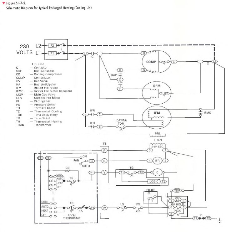
Your observation confirms that indeed the outdoor fan is not running. You also confirm that both the compressor and indoor fan are running. Based on your observations and an analysis of the unit’s wiring diagram (Figure SP-7-2), it is obvious that most of the circuits can be eliminated as the source of the problem, except for the outdoor fan motor circuit. Because the symptoms allowed you to easily identify the defective circuit, you would continue to troubleshoot the outdoor fan motor circuit to find the faulty component using the hopscotch method of troubleshooting as described in Service Procedure SP-8.
For our example, assume the internal overload in the fan was open, stopping it from running- You observe that overgrown bushes surrounding the outdoor unit are restricting the airflow through the coil. On extremely hot days, when the fan runs most of the time, this airflow restriction is enough to cause the motor to overheat and open its internal overload, stopping the motor. On cooler days, when the motor did not run as often, motor operation remained normal. Clearing the bushes away from the coil would solve this problem.
The schematic diagram for the heating/cooling unit shown in Figure SP-7-2 is typical o f those you will encounter in the field. Figure SP-7-3 shows a simple tree diagram for troubleshooting heating/cooling units. The troubleshooting guidelines given in the tree diagram are keyed to the detailed procedures given at the end of this section. Both the tree and the troubleshooting procedures can be used to troubleshoot most heating/cooling equipment. You would use them when the symptoms of an electrical problem do not allow you to easily find the faulty circuit, such as in the previous example.