| Step | Expected Result/Action |
|---|---|
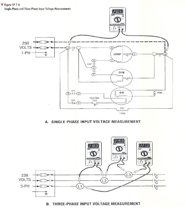
| Measure input voltage on a single-phase system as follows: Turn power off. Set up the VOM/DMM to measure AC voltage on a range that is higher than the highest voltage expected. (Refer to the unit nameplate.) Connect the VOM/DMM between test points LI and L2 as shown in Figure SP-7-4, View A. Turn power on, then measure and record the input voltage level. Turn power off and disconnect VOM/DMM. | Measured voltage should be between the "permissible max. and min." values given on the unit nameplate. If none are given, allow a tolerance of +10% from the power supply volts value marked on the unit nameplate. For example, a unit with a nameplate single voltage rating of 230 volts should have an input voltage that ranges between 207 volts and 253 volts (±10% of 230 volts). Operating a unit continuously at either voltage extreme (+10% or -10%) is poor practice and shorter component life is to be expected. If voltage is excessively high or low, check for excessive wire length, poor contact, etc. If all potential local problems are ruled out, contact the electric utility. |
| Measure input voltage on a three-phase system as follows: Turn power off. Set up the VOM/DMM to measure AC voltage on a range that is higher than the highest voltage expected. {Refer to the unit nameplate.) Connect VOM/DMM between test points LI and L2, as shown on Figure SP-7-4, View B. Turn power on, then measure and record the input voltage. Repeat the input voltage measurement for the remaining two phases by measuring between test points L2 and L3, and L3 and LI, as shown in Figure SP-7-4, View B. Turn power off and disconnect VOM/DMM. | Measured voltage should be between the "permissible max. and min." values given on the unit nameplate. If none are given, allow a tolerance of ±10% from the power supply volts value given on the unit nameplate. Note that operating a unit continuously at either voltage extreme (+10% or -10%) is poor practice and shorter component life is to be expected. If voltage is excessively high or low, check for excessive wire length, poor contact, etc. If all potential local problems are ruled out, contact the electric utility. |
| Calculate percent of voltage imbalance for a three-phase system using the formula below. % Voltage Imbalance = Maximum Voltage Deviation Average Voltage x 100 | The percent voltage imbalance should be 2% or below. (See the example calculation below.) If the voltage imbalance exceeds 2%, contact the electric utility. Example of % voltage imbalance calculation Voltage measured L1-L2 2 1 8 volts Voltage measured L2-L3 2 1 9 volts Voltage measured L3-L J 221 volts Average voltage 658 volts + 3 = 219.3 Difference between the average voltage and the measured voltage: L l-L2 = 2 1 9 .3 V -218.0/ = 1.3V ___ L2-L3 = 2 1 9.3V- 2 1 9.0V = 0.3V L3-L1 = 221.0V -2 1 9 .3V = 1.7V % Imbalance = Maximum Voltage Deviation ?+? Average Voltage x 100 % Imbalance = 1 .7 + 2 1 9 .3 x 100 = 0.8% Since imbalance is less than 2%, the input voltage balance between phases is good. |