Multimeters can measure the resistance in ohms (£2) of all or any part of the circuit. Resistance values o f HVAC components can vary greatly from a few ohms to several million ohms. Most multimeters can measure below one ohm; some measure as high as 300 million (meg) ohms. Multimeters contain their own battery power for use when making resistance measurements. Resistance measurements must be made with the equipment power off and all capacitors in the circuit discharged, otherwise damage to the meter can result. Some multimeters have high voltage protection (500 volts or more) in the resistance mode in case o f accidental contact with voltages. This level of protection varies greatly between models.
Resistance measurements are usually made to determine the resistance of a Load; e.g., relay, contactor or starter coils; motor windings; and electronic components such as diodes and resistors.
Make resistance measurements as follows (Figure 3-25).
1. Turn off power to the equipment or circuit.
2. Select resistance (ohms or Q) using the function/range switch.
If using an analog meter, select the lowest resistance range that will accurately read the value. If unknown, start at the highest, then work your way down to a lower range when making the measurement. For accuracy, select the range where the pointer reads in the mid to upper half of the scale.
3. Plug the test probes into the meter jacks. Usually the black probe is connected to the common (COM) or minus (-) jack and the red probe to the plus ( + ) or V-Ohm jack. If using an analog meter, always zero the meter before the first measurement and whenever you change range scales. To zero the meter, touch the tips of the test probes together, then use the zero adjustment knob (Figure 3-23) to set the pointer to zero.
4. Before measuring resistance, make sure to electrically isolate
the component being measured by disconnecting at least one lead of the component from the circuit- This is important in order to get an accurate resistance reading. Otherwise, the meter will read the combined resistance of all components that are connected in parallel with the component to be measured.
5. Connect the test probe tips across the component or portion of the circuit you want to measure.
6. View the reading on the digital readout or analog scale.
If using a digital meter, be sure to note the unit of measurement: ohms (Q), kilohms (kQ), or megohms (MQ) shown for the reading.
If using an analog meter, determine the resistance value by multiplying the scale reading by the number (R x 1, R x 10, etc.) next to the function/range switch.
As shown on Figure 3-26, the reading “5 ” is multiplied by the selector setting R x 1, yielding a resistance of 5 ohms. At the R x 100 setting, the same reading would be 500 ohms, and at the R x 10,000 setting, it would be 50,000 ohms.
A continuity check is a go/no-go resistance test used to test for open and closed circuits. Examples are shown in Figure 3-27.
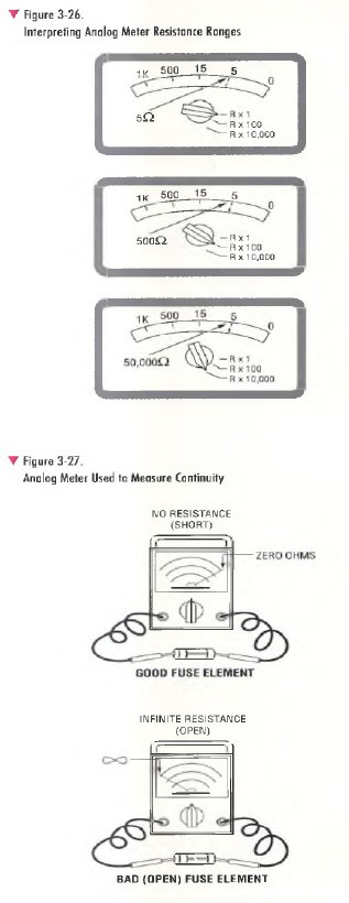
A good fuse offers no resistance. If using an analog meter for the measurement as shown, the pointer moves all the way to the right, displaying continuity (zero ohms). If using a digital meter, it may beep to indicate that continuity was detected and the digital readout will also show zero ohms. The level of resistance required to trigger the digital beeper varies from model to model. This beep feature is helpful because it allows continuity checks to be made without having to look at the meter reading.
If the fuse is bad, it has no path for current flow. The analog meter has no deflection and the pointer remains at the far left as shown, displaying infinite resistance or infinity (°°). This indicates an open circuit. If using a digital meter, it would indicate infinite resistance by reading “OL” , flashing digits, or a similar message on the display indicating that the resistance is greater than the digital meter can measure.
Unless specified by the manufacturer, the VOM/DMM should not be used to make resistance measurements on an electronic device. This is because when set up to measure resistance, the test voltage supplied by the internal battery of the VOM/DMM may exceed the safe voltage level for the electronic device under test, resulting in damage to the device.