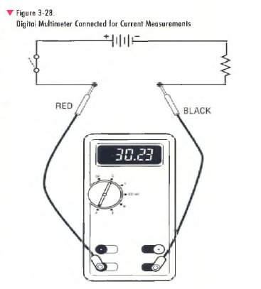
Making current measurements with a multimeter is different than making other measurements with a multimeter. Current measurements are made in series, unlike voltage or resistance measurements, which are made in parallel. The entire current being measured flows through the meter. As previously discussed, the clamp-on ammeter is used to make most of the higher A C current measurements needed for HVAC servicing. The multimeter is used mainly to make low-level DC current measurements in electronic control circuit modules.
Make current measurements as follows (Figure 3-28):
1. Turn off power to the equipment or circuit. Disconnect a component or circuit to make a place where the multimeter probes can be inserted in series with the circuit to be measured.
2. Use the function/range switch to select DC amps. Select A C amps if A C is being measured.
If using an analog meter, always select the highest range. If necessary, switch to a lower range when making the measurement. For accuracy, select the range where the indicator reads in the upper half of the scale face.
3. Plug the test probes into the meter jacks. Usually the black probe is connected to the common (COM) or minus (—) jack. Connect the red probe to the input jack marked for the DC range of the expected reading, the plus (+ ) jack, or other jack as applicable.
4- Connect the test probe tips in series with the circuit so that all current flows through the meter. Measurement is easier if alligator clips are used to connect the meter leads to the circuit. Be sure to turn the circuit power off before connecting the alligator clips.
If using an analog meter to measure DC current, you must observe correct polarity (+/—)- Connect the red test probe to the positive side of the circuit and the black test probe to the negative side or circuit ground. If you reverse the connections, the meter movement goes off the scale in the opposite direction and damage to the meter can result. If using a digital meter with auto polarity, the reading will display a minus sign to indicate negative polarity.
5. Turn the circuit power on. View the reading on the digital meter readout. Be sure to note the unit o f measurement indicated. If using an analog meter, read the voltage value indicated by the pointer on the DC current scale. Make sure to use the scale that matches the selector switch current setting.
