OPERATION:
These units use an integrated control and motor that is programmed for variable-capacity operation. The fan speed is controlled by the iComfort Wi-Fi® thermostat.
CHECKOUT:
VAC Voltage Check
Check for 208/240 VAC power at inverter contactor (red wires) (see figure 46).
With unit operating, check for main VAC to motor and outdoor control VDC output to motor:
1. No voltage present – Check main power
2. Voltage present – Perform DC volt checks (19 -23 VDC between FAN PWM and COM) (see figure 46).

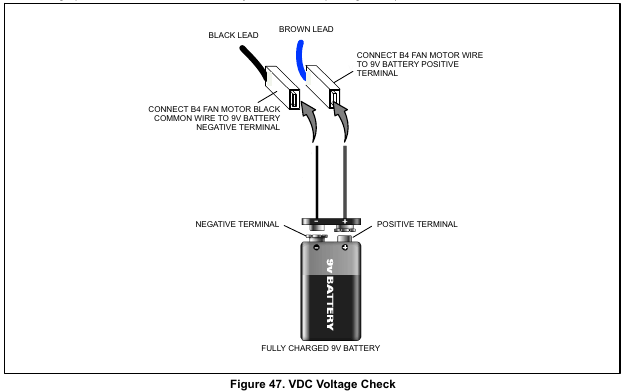
VDC Voltage Check:
Check for VDC out of Fan PWM and COM. VDC output reading is determined by the percentage of room thermostat demand.
1. No voltage present – Remove wires from control and check for VDC. If there is no voltage present, then replace out door control.
2. Voltage present – Perform a 9-volt battery test on motor (see figure 47).
STATUS OR ERROR CODES:
There is no feedback from the outdoor fan motor to the outdoor control therefore no status or error codes are displayed on either the outdoor control or iComfort Wi-Fi® room thermostat.
NOTE – If the outdoor fan does not operate at the correct RPM, or does not start, the system will shut be down by other protection components such as the high and low pressure switches which will generate error code(s).