Figure 2-4 shows how the manufacturer represents the location of the various furnace devices. The solid lines indicate the line voltage to be installed. The dotted lines are the low voltage to be installed when the furnace is put into service.
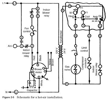
The motor is four speed. It has different colored leads to represent the speeds. You may have to change the speed of the motor to move the air to a given location. Most motors come from the factory with a mediumhigh speed selected. The speed is usually easily changed by removing a lead from one point and placing it on another, where the proper color is located. In the schematic of Fig. 2-5, the fan motor has white lead connected to one side of the 120-V line (neutral) and the red and black are switched by the indoor blower relay to black for the cooling speed and red for the heating speed. It takes a faster fan motor to push the cold air than for hot air because cold air is heavier than hot air.
In Fig. 2-5, the contacts on the thermostat are labeled R, W, Y, and G. R and W are used to place the thermostat in the circuit. It can be switched from W to Y manually by moving the heat-cool switch on the thermostat to the cool position.
Notice in Fig. 2-5 that the indoor blower relay coil is in the circuit all the time when the auto-on switch on the thermostat is located at the on position. The schematic also shows the cool position has been selected manually, and the thermostat contacts will complete the circuit when it moves from W1 to Y1.
In Fig. 2-4, note that the low-voltage terminal strip has a T on it. This is the common side of the low voltage from the transformer. In Fig. 2-5, the T is the common side of the low-voltage transformer secondary. In Fig. 2-4, the T terminal is connected to the compressor contactor by a wire run from the terminal to the contactor. Note that the other wire to the contactor runs from Y on the terminal strip. Now go back to Fig. 2-5, where the Y and T terminals are shown as connection points for the compressor contactor. Are you able to relate the schematic to the actual device? The gas valve is wired by having wire T of the terminal strip attached to one side of the solenoid and a wire run from the limit switch to the other side of the solenoid.
Figure 2-6 shows how the wiring diagram comes from the factory. It is usually located inside the cover for the cold-air return. In most instances, it is glued to the cover so that it is handy for the person working on the furnace whenever there is a problem after installation.


