With halocarbon systems (Refrigerants 12, 22, 502, etc.) the oil and refrigerant are miscible (capable of being mixed) under certain conditions. Oil is quite soluble in liquid Refrigerant 12 and partially so in liquid Refrigerant 22 and 502. For example, for a 5% (by weight) solution of a typical napthenic (a petroleum-based oil) oil in liquid refrigerant, the oil will remain in solution down to about ?75°F (?59°C) for Refrigerant 12, down to about 0°F (?18°C) for Refrigerant 22, and down to about 20°F (?7°C) for Refrigerant 502. Depending upon the type of oil and the percentage of oil present, these figures can vary. However, based on the foregoing, we can assume that for the majority of Refrigerant-12 systems the oil and refrigerant are completely miscible at all temperatures normally encountered. However, at temperatures below 0°F (?18°C) with Refrigerant 22 and a 5% oil concentration and temperatures below 20°F (?7°C) with Refrigerant 502 and a 5% oil concentration, a liquid phase separation occurs. An oil-rich solution will
appear at the top and a refrigerant-rich solution will lay at the bottom of any relatively placid remote bulb chamber.
Oil in a halocarbon-flooded evaporator can produce many results. Oil as a contaminant will raise the boiling point of the liquid refrigerant. For example, with Refrigerant 12, the boiling point increases approximately 1°F [(0.56°C)] for each 5% of oil (by weight) in solution. As in an ammonia system, oil can foul the heat-transfer surface with a consequent loss in system capacity. Oil can produce foaming and possible carryover of liquid into the suction line. Oil can also affect the liquid-level control. With a float valve you can normally expect the liquid level in the evaporator to decrease with increasing concentrations of oil in the float chamber. This is due to the difference in density between the lighter oil in the chamber and the lower balance leg and the heavier refrigerant/oil mixture in the evaporator. A lower column of dense mixture in the evaporator will balance a higher column of oil in the remote chamber and piping. This is similar to a “U” tube manometer with a different fluid in each leg.
With the level-master control, the heat-transfer rate at the bulb is decreased, producing overfeeding and possible flood-back. What can be done? First of all, the oil concentration must be kept as low as possible in the evaporator, surge drum, and remote insert bulb chamber (if one is used). With Refrigerant 12, since the oil/refrigerant mixture is homogenous, it can be drained from almost any location in the chiller, surge drum, or remote chamber that is below the liquid level. With Refrigerants 22 and 502, the drain must be located at or slightly below the surface of the liquid, since the oil-rich layer is at the top. There are many types of oil-return devices:
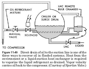
? Direct drain into the suction line
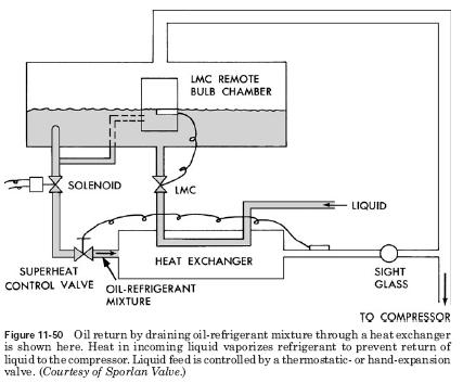
? Drain through a high-pressure, liquid-warmed heat exchanger
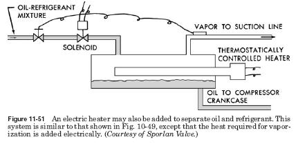
? Drain through a heat exchanger with the heat supplied by an electric heater
Draining directly into the suction line, as shown in Fig. 11-49, is the simplest method. However, the hazard of possible flood-back to the compressor remains.
Draining through a heat exchanger, as indicated in Fig. 11-50, is a popular method. The liquid refrigerant flood-back problems are minimized by using the warm liquid to vaporize the liquid refrigerant in the oil/refrigerant mixture.
The use of a heat exchanger with an insert electric heater, as shown in Fig. 11-51, is a variation of the preceding method.
In all of the return arrangements discussed, a solenoid valve should be installed in the drain line and arranged to close when the compressor is not in operation. Otherwise, liquid refrigerant could drain from the low side into the compressor crankcase during the off-cycle.
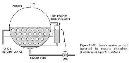
If the insert bulb is installed directly into the surge drum or chiller, oil return is necessary only from this point. However, the insert bulb is sometimes located in a remote chamber that is tied to the surge drum or chiller with liquid- and gas-balance lines. Then oil return should be made from both locations, as shown in Figs. 11-49, 11-50, and 11-52.
Why ammonia pump does not work?