Relays are magnetic switches used in the AC system to send power to loads that draw lots of current, such as the compressor clutch and the blower motor. After testing the fuses, the relay is a very good place to begin testing because it can be accessed easily at the relay box or power distribution center. Below are some strategies that can be used when testing electrical circuits at the relay.
Tips for Testing Relays
1. Listen for a click when the circuit is turned on and off.
2. Substitute a known good relay in place of the relay that is not working.
3. Use a toggle switch relay to see if the circuit can be energized with the toggle switch.
4. Use a fused jumper wire across the load side of the relay to see if the circuit can be energized by bypassing the relay.
5. Test the relay in a static method by using the ohmmeter on the DMM. The coil should have about 60 to 100 ohms and the normally open contact should be OL, which means the contacts are not connected.
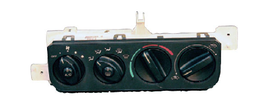
More modern HVAC control head designs mainly control electrical operation of the system and are typically not serviceable. If these control heads develop a problem, then the complete assembly must be
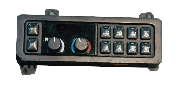
HVAC systems that automatically control the desired temperature in the cab are called automatic temperature control. These systems use HVAC control heads that have digital displays and operate in an advanced
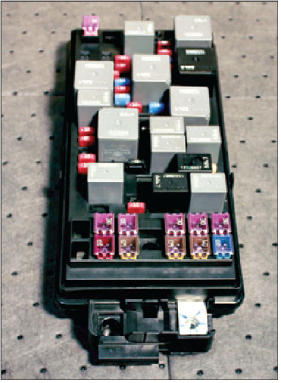
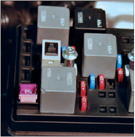
The power distribution center is a convenient location for various sizes and types of fuses as well as the many relays that are needed on late-model vehicles. Power distribution centers are located under the hood, while the fuse panel is located inside the vehicle. Some vehicles will have multiple power distribution centers and fuse panels. This power distribution center has ISO relays as well as half ISO relays. Half ISO relays are smaller and take up less space, which is popular on newer vehicles that have many more electronic options. ISO relays have standardized pin configurations that have been spelled out by the International Standards

There are several pin configurations for relays that are used on various manufacturers’ vehicles. There are four-pin relays that have two terminals for the coil and two terminals for the load side contact. Some relays use one more terminal that operates as a normally closed switch. The larger relay is an ISO relay and can deliver about 30 to 40 amps to a load, while the three smaller relays are half ISO style and can deliver about 20 amps to a load. The smaller relays are popular because of their smaller-size body and how more of them can fit in a power
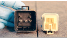
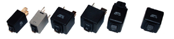
These relays are configured a little different than the ones in the photo above. The relay on the left is a five-pin relay and the relay on the right is a four-pin
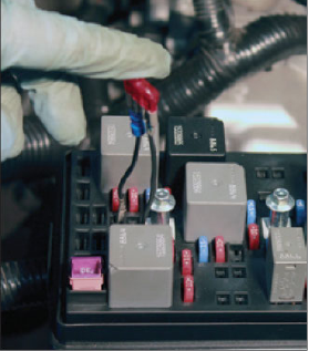
The bypass relay is being used in the power distribution center to activate the AC compressor clutch. The original relay was removed and the bypass relay was installed instead. The toggle switch is switched to on, which should supply power to the AC compressor
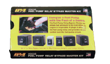
Bypass relays are very handy to use when troubleshooting relay-powered circuits. This set contains six of the most common pin configurations being used. These devices can be used by substituting them for the relay that is being
Bypass relays can be used to easily turn on relay-powered circuits during the diagnosis process. These devices are installed in place of the stock relay and then are turned on with a toggle switch mounted on top of the unit. If the load turns on when the toggle switch is flipped, then the load side of the relay circuit is
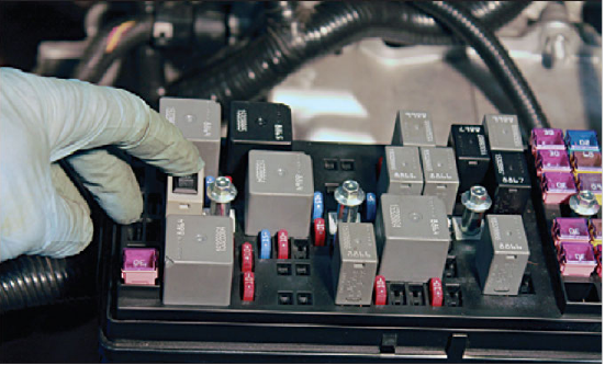
By pressing the toggle switch on this bypass relay, the circuit is energized. This is a logical location to use when diagnosing circuits that are powered by a relay because it breaks the circuit in half and energizes the load side of the circuit. If the load turns on with this technique, then the control side of the circuit should be
A fused jumper wire can be used to bypass switches and relays. This fused jumper is installed in terminals 30 and 87 of this four-pin relay. This action safely supplies power to the AC compressor clutch. Never connect any jumper wires in terminals 85 and 86 because damage to the power distribution center can